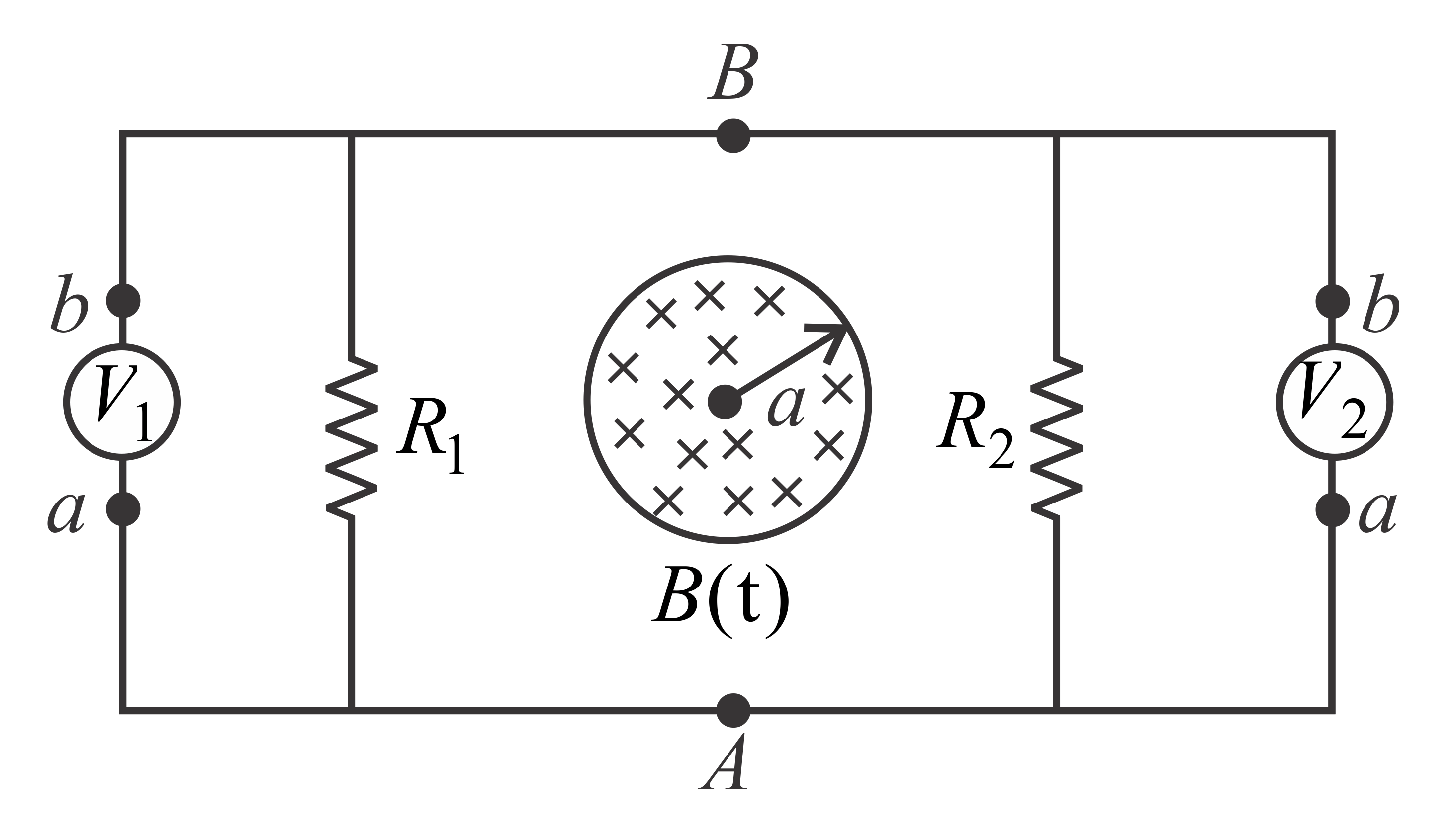
Q.
The circuit shown in the figure consists of two resistances $R_{1}$ & $R_{2}$ connected to two ideal voltmetres $V_{1}$ & $V_{2}$ . Assume that a voltmeter reads $\Delta V=-\int\limits _{a}^{b}\vec{E}.d\vec{l}$ between its terminals. A time-varying magnetic field $B\left(\right.t\left.\right)=B_{0}t$ (where $B_{0}$ is a positive constant of proper dimensions and $t$ is time) exists in a circular region of radius a and it is directed into the plane of the figure. The reading of voltmeter $V_{2}$ is

NTA AbhyasNTA Abhyas 2022
Solution:
