Thank you for reporting, we will resolve it shortly
Q.
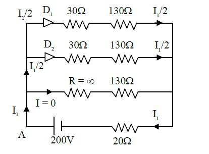
In the given figure, each diode has a forward bias resistance of $30\, \Omega$ and infinite resistance in reverse bias. The current $I _{1}$ will be:
JEE MainJEE Main 2021Semiconductor Electronics: Materials Devices and Simple Circuits
Solution:
As per diagram,
Diode $D_{1} \,\&\, D_{2}$ are in forward bias i.e. $R=30 \,\Omega$
whereas diode $D_{3}$ is in reverse bias i.e. $R=$ infinite
$\Rightarrow $ Equivalent circuit will be
Applying KVL starting from point $A$
$-\left(\frac{ I _{1}}{2}\right) \times 30-\left(\frac{ I _{1}}{2}\right) \times 130- I _{1} \times 20+200=0$
$\Rightarrow -100 I _{1}+200=0$
$I _{1}=2$